 The Basics of Globe Valves: What You Need to Know. The term globe valve applies to a valve whose body is shaped like a globe or has characteristics like those of a globe.
Globe valves are generally suitable for throttling applications, as the valve design determines how closely the flow can be regulated.
The part that controls the flow in this valve is the disc, which is attached to the stem.
The disc fits precisely into the valve seat.
When the valve is open, the liquid passes through the space between the edge of the disc and the seat.
Generally, the maximum differential pressure across the valve disc should not exceed 20 percent of the maximum upstream pressure or 200 psi (1380 kPa), whichever is less.
Special TRIM of valves may be designed for applications that exceed these differential pressure limits.
The Basics of Globe Valves
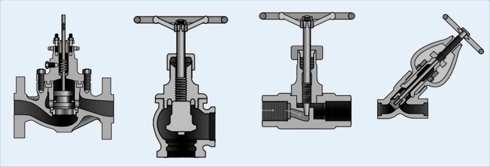
The Basics of Globe Valves: What You Need to Know. General overview of of a typical globe valve:
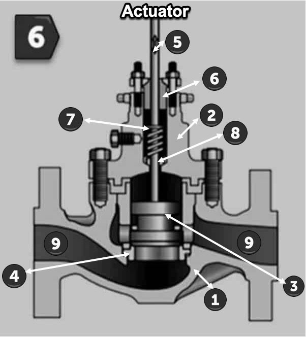
- Body: The body of the globe valve is the outer casing that houses all the internal components.
It is typically made of cast iron, ductile iron, cast steel, forged steel, or other materials, depending on the working conditions and the type of fluid being handled. The body is designed to withstand the pressure and temperature requirements of the application. - Bonnet: The bonnet is the cover or cap that is bolted or screwed to the top of the valve body.
It serves two main purposes: it provides a pressure-tight seal to prevent leakage, and it houses the stem and the valve disk assembly. The bonnet may be of a different material than the body, especially in high-temperature applications. - Disc (Disk): The disc, also known as the disk, is the movable element inside the valve. It controls the flow of fluid through the valve by moving up and down as the valve is operated. The disc may have various designs, such as flat, plug, or parabolic, depending on the specific application and control requirements.
- Seat: The seat is a fixed component located within the valve body against which the disc comes in contact when the valve is closed. It provides a tight shut-off, preventing any leakage of fluid when the valve is in the closed position.
Seats are usually made of resilient materials such as rubber or Teflon, or they may be made of metal or metal alloys for high-temperature and high-pressure applications. - Stem: The stem is a slender, elongated rod that connects the actuator (handwheel, actuator motor, etc.) to the disc. When the actuator is operated, it causes the stem to move up or down, which in turn raises or lowers the disc to regulate the flow of fluid through the valve.
The stem is designed to be leak proof as it passes through the bonnet, and it may have packing or other sealing mechanisms to prevent fluid leakage along the stem. - Gland: The gland is a component that compresses the packing material around the stem, creating a seal. It is usually tightened with bolts or gland nuts to maintain the proper compression and prevent leakage.
- Packing: Globe valves typically use packing material around the stem to create a seal and prevent fluid from leaking along the stem. The packing material is usually made of flexible materials like graphite, PTFE (Teflon), or other suitable compounds.
- Backseat: Some globe valves are designed with a backseat feature, which is a secondary stem packing arrangement located at the top of the stem.
When the valve is fully open, the backseat feature allows maintenance personnel to replace the stem packing without taking the valve out of service. - Ports: Globe valves have two ports, an inlet (where fluid enters) and an outlet (where fluid exits).
The position of the disc in relation to the seat regulates the flow of fluid between these ports. - Actuator: The actuator is the mechanism used to operate the valve.
It can be a manual handwheel, an electric motor, pneumatic actuator, or hydraulic actuator, depending on the application and the level of automation required.
What you need to know
Types of globe valves include:
Angle globe valve
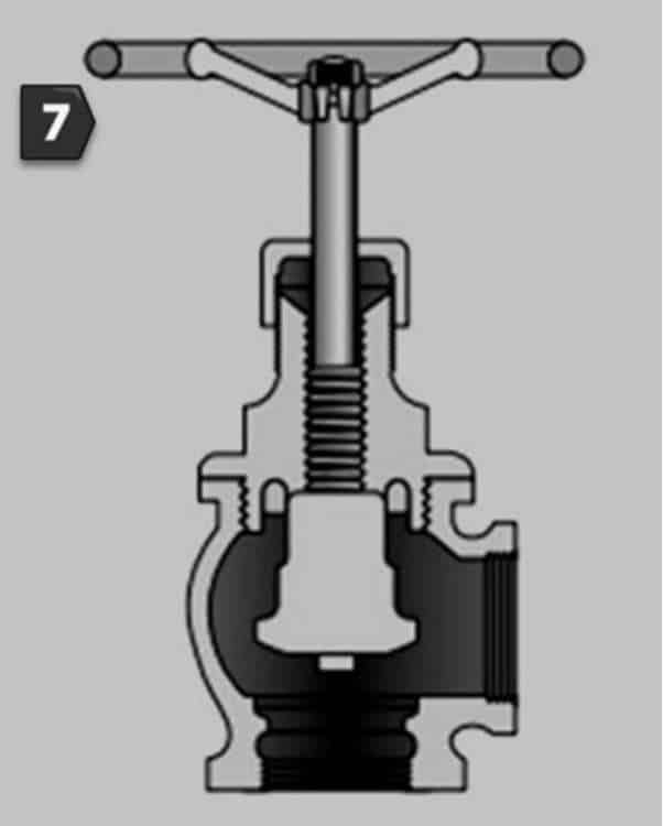
An angle globe valve is a specific configuration of the globe valve that is designed to change the direction of flow in a pipeline. It is also known as an “angle-type” globe valve or simply an “angle valve.”
Like the standard globe valve, it consists of a movable disk or plug element and a stationary ring seat, but its inlet and outlet ports are oriented at an angle to each other, typically at a 90-degree angle.
The angle design makes it particularly useful in applications where the pipeline requires a change in flow direction or when space limitations prevent the installation of a straight-through globe valve.
By using an angle globe valve, the flow of fluid can be redirected at a right angle without the need for additional fittings or elbows.
Applications of Angle Globe Valves:
- Space-constrained installations: In situations where there is limited space, such as in compact piping systems, the angle globe valve can provide a more convenient solution to change the direction of flow without the need for additional fittings.
- Piping systems with restricted access: Angle globe valves are beneficial in locations where the valve needs to be installed close to a wall or obstruction. The angled design allows for easier access to the valve for maintenance and operation.
- Flow control and throttling: Like standard globe valves, angle globe valves are well-suited for applications that require precise flow control or throttling due to their linear flow characteristics.
- Heating and cooling systems: Angle globe valves are commonly used in heating and cooling systems to control the flow of hot or chilled water, steam, or other fluids.
- Process industries: They find applications in various process industries such as chemical, petrochemical, oil and gas, where flow direction changes may be required as part of the process.
The image shows a section of an angle globe valve
See figure N°7.
Needle Valve
Understanding the Basics of Globe Valves.
A needle valve is a type of valve that provides precise control over the flow of fluid through a piping system.
The needle valve’s design permits fine adjustments of flow rates, making it suitable for applications that require precise throttling.
Structure and Operation:
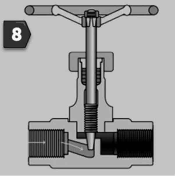
- The needle valve consists of a threaded stem with a pointed conical or needle-shaped at the end. This stem is often called “needle”.
- When the valve is fully open, the needle is retracted and fluid can flow through the relatively wide opening.
- As the valve is gradually closed by turning the stem, the tapered needle starts to obstruct the flow path.
- The fluid must pass through the increasingly narrow gap between the needle and the valve seat, thus regulating the flow rate.
- Operators can achieve the desired flow rate for a given application by utilizing this precise control for gradual adjustments.
Applications:
- The hydraulic power plants use the needle valves as a bypass of the butterfly or spherical valves.
- First, operate the needle valve, which can work better than the main valve at large pressure differences without cavitation, and once the main valve is at balanced pressures at the ends, the needle valve is opened, avoiding the water hammer in the installation.
- In laboratories, analytical instruments, and fluid sampling systems, needle valves are commonly employed for accurate flow control.
- They have applications in a variety of industries, including chemical transformation, petrochemical, oil and gas, pharmaceuticals and aerospace, among others.
- Needle valves are frequently used in hydraulic and pneumatic systems to control the flow of gases or liquids.
Advantages and Limitations:
Advantages:
- Accurate flow control: Needle valves provide fine adjustments for accurate flow control.
- Compact design: its compact and simple structure makes it suitable for space-constrained installations.
- The sealing capabilities of needle valves are excellent when properly operated and maintained.
Limitations:
- Flow: Because of the low flow through the needle and seat, needle valves are not suitable for high flow applications.
- Sensitive to clogging: The small flow path may become clogged if the fluid contains debris or particulate matter.
The image shows a section of a Needle Valve
See figure N°8.
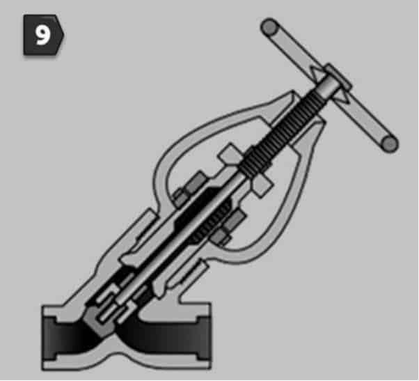
Wye Valve
It is an alternative to the high-pressure drop of the traditional globe valve.
The seat and stem have an angle of approximately 45 degrees, which gives a straighter flow path at full opening thus offering less resistance to flow.
They are widely used for regulation during start-up operations.
For its smooth flow pattern, a Wye – valve is preferable for use with erosive fluids.
The image shows a section of a Wye Valve
See figure N°9.
Flow Direction of Globe Valves
The valve seat parallel to the flowline is an important characteristic of the globe valve.
This feature makes the valve effective during product throttling as well as giving minimal disk and seat erosion.
In most installations the fluid is routed into the valve body from under the valve seat and disc.
This flow direction uses the pressure of the fluid to aid in the opening operation of this valve. It also reduces the wear of the seats and the valve disk.
An exception however is when high temperature steam is routed through this valve.
The extreme temperature of the vapor coming into contact with the valve seat from below creates a significant temperature difference from the top of the seat and the disc.
This temperature difference between the valve seats and the disc causes leaks.
Therefore, when high temperature steam is routed through a globe valve, it is routed into this valve from the top of the disc.
Globe valve operation
The Basics of Globe Valves: What You Need to Know. The globe valve must never be set in the fully open position.
After a valve is fully opened, the handwheel or actuating lever must be turned toward the closed position approximately one-half turn.
Unless this is done, the pressure is likely to cause the valve to stick in the open position, making it difficult, if not impossible, to close the valve.
Many gates are damaged in this manner.
Read our next article in which the non-return valves are detailed.
The Basics of Globe Valves: What You Need to Know – Calculate Man Hours